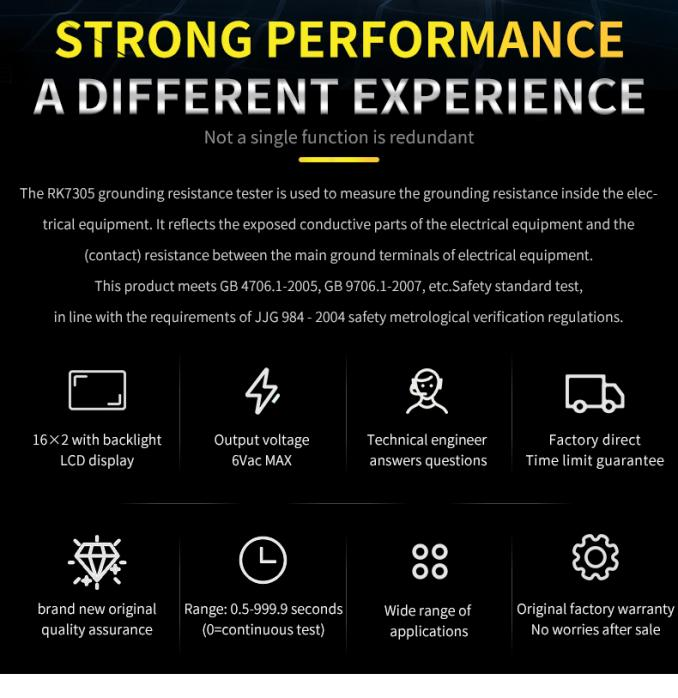
The term “ground resistance” is a poorly defined word. In some standards (such as safety standards for household appliances), it refers to the grounding resistance inside the equipment, while in some standards (such as in the grounding design code), it refers to the resistance of the entire grounding device. What we are talking about refers to the grounding resistance inside the equipment, that is, the grounding resistance (also called grounding resistance) in general product safety standards, which reflects the exposed conductive parts of the equipment and the overall grounding of the equipment. resistance between terminals. The general standard stipulates that this resistance should not be greater than 0.1.
The grounding resistance means that when the insulation of the electrical appliance fails, the easily accessible metal parts such as the electrical enclosure may be charged, and a reliable grounding protection is required for the safety of the electrical appliance user. The grounding resistance is an important indicator to measure the reliability of the electrical grounding protection.
The grounding resistance can be measured with a grounding resistance tester. Since the grounding resistance is very small, usually in the tens of milliohms, it is necessary to use four-terminal measurement to eliminate the contact resistance and obtain accurate measurement results. The ground resistance tester is composed of a test power supply, a test circuit, an indicator and an alarm circuit. The test power supply generates an AC test current of 25A (or 10A), and the test circuit amplifies and converts the voltage signal obtained by the device under test, which is displayed by the indicator. If the measured grounding resistance is greater than the alarm value (0.1 or 0.2), the instrument will sound Light alarm.
Program-controlled grounding resistance tester testing precautions
When the program-controlled grounding resistance tester measures the grounding resistance, the test clip should be clamped to the connection point on the surface of the accessible conductive part. The test time is not easy to be too long, so as not to burn out the test power supply.
To accurately measure the grounding resistance, the two thin wires (voltage sampling wires) on the test clip should be removed from the voltage terminal of the instrument, replaced with two other wires, and connected to the connection point between the measured object and the current test clip to completely eliminate the influence of contact resistance on the test.
In addition, the grounding resistance tester can also measure the contact resistance of various electrical contacts (contacts) in addition to measuring grounding resistance.
Merrick Instruments’ Programmable Earth Resistance Tester RK9930 The maximum test current is 30A;RK9930A The maximum test current is 40A;RK9930B The maximum output current is 60A;For the grounding resistance test, under different currents, the upper limit of the test resistance is calculated as follows:
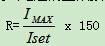
When the calculated resistance R is greater than the maximum resistance value of the tester, take the maximum resistance value.
What are the advantages of the program-controlled earth resistance tester?
Programmable Earth Resistance Tester The sine wave generator is mainly controlled by the CPU to generate a standard sine wave, and its waveform distortion is less than 0.5%. The standard sine wave is sent to the power amplifier circuit for power amplification, and then the current is output by the current output transformer. The output current passes through the current transformer. Sampling, rectification, filtering, and A/D conversion are sent to the CPU for display. Voltage sampling, rectification, filtering, and A/D conversion are sent to the CPU, and the measured resistance value is calculated by the CPU.
Programmable Earth Resistance Tester Compared with the traditional voltage regulator type grounding resistance tester, it has the following advantages:
1. Constant current source output; set the current to 25A, within the test range of this series of testers, during the test, the output current of the tester is 25A; the output current does not change with the load.
2. The output current of the program-controlled grounding resistance tester is not affected by the power supply voltage. In the traditional voltage regulator type grounding resistance tester, if the power supply fluctuates, its output current will fluctuate with it; this function of the program-controlled grounding resistance tester cannot be achieved by the voltage regulator type grounding resistance tester.
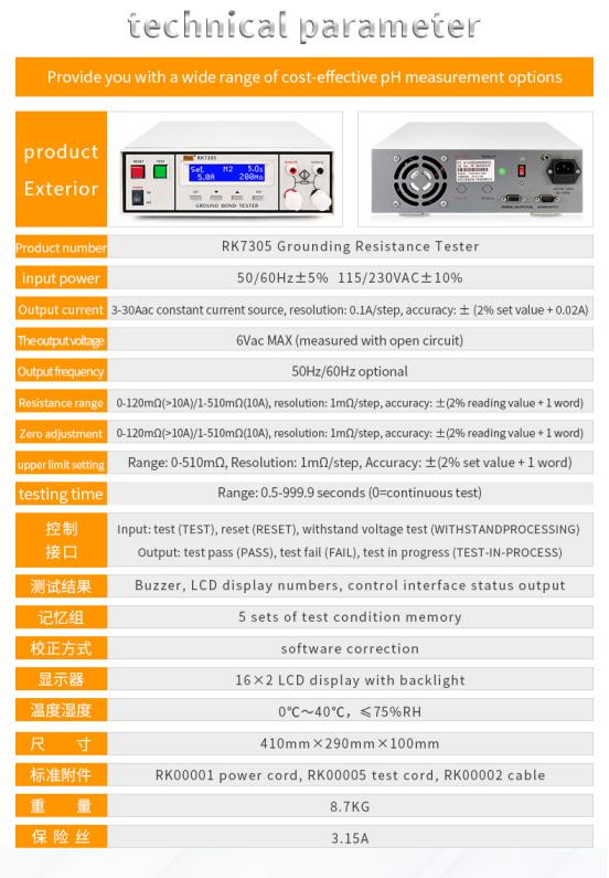
3.The RK7305 grounding resistance tester has a software calibration function; if the output current, display current and test resistance of the tester exceed the range given in the manual, then the user can calibrate the tester according to the operation steps of the user manual.RK9930 series Can be automatically calibrated and not affected by the environment
4.The output current frequency is variable;RK9930、RK9930A、RK9930B The output current of the grounding resistance tester has two frequencies to choose from: 50Hz/60Hz, which can meet the needs of different test pieces.
Testing of safety performance of household appliances
1. Insulation resistance test
The insulation resistance of household electrical appliances is one of the important signs to evaluate the quality of their insulation. Insulation resistance refers to the resistance between the live part of the household appliance and the exposed non-live metal part. With the rapid development of the household appliance industry and the great increase in the popularity of such products, in order to ensure the personal safety of users, the requirements for the insulation quality of household appliances are becoming more and more strict.
Insulation resistance measuring instrument operation method
1. Plug in the power supply, turn on the power switch, the power indicator light is on;
2. Select the working voltage and press the required voltage button;
3. Select the alarm value;
4. Select the test time (for the digital display series, the pointer type does not have this function);
5. School infinity (); (RK2681 series can support)
6. For full scale calibration, connect the calibration resistor attached to the measuring end, and adjust the full scale calibration potentiometer so that the pointer points to full scale.
7. Connect the measured object to the measuring end and read the insulation resistance.
Insulation resistance tester testing precautions
1. It should be fully preheated before measurement to drive off the moisture in the machine, especially in the humid weather in the rainy season in the south.
2. When measuring the insulation resistance of the electrical equipment in operation, the equipment should be taken out of the running state first, and the measurement should be made quickly before the equipment hotbed drops to room temperature to prevent the measured value from being affected by condensation on the insulating surface.
3. The electronic measuring instrument should be in a non-working state, and the instrument switch should be in the on state to measure its insulation resistance, and the circuits or components that are not related to the tested part should be disconnected during the measurement.
4. In order to avoid the measurement value being affected by the poor insulation of the measurement connecting wire, the insulation of the quasi-connecting wire should be checked frequently and not twisted against each other.
Post time: Oct-19-2022


